Micro Project Report
on
The component used in Universal Coupling 3D Drawing drawing by using Solid Modelling software
Brief Introduction :-
Universal joint is a positive mechanical joint used for connecting shafts, whose axes are inclined at an angle to each other. It is also known as universal coupling, U-joint, Cardan Joint and Hooke’sJoint. It compensates ang ular misalignment between the shafts in any direction.
Aim of microproject
1 . Prepare technical report
2.show the attitude of enq uiry
3.work independent ly for responsibility
4. participate effectively in group work
5. wo rk persistent ly achieve the target
|
ACTION PLAN :
|
|||||||||||||||||||||||||||
| Sr.No. | Resource Required | Specification | Quantity | Remark |
|---|---|---|---|---|
| 1 | Internet | |||
| 2 | Software | Katia V5 | 1 | |
| 3 | Printer | Canon | 1 | |
| 4 | Paper | Bond | 22 | |
| 5 | Laptop | HP | 1 |
Title :- “ -Component used in Universal Coupling 3D Drawing drawing by using Solid Modelling software
Aims/Benefits of the Micro-Project :- A universal joint is a joint or coupling in a rigid rod that allows the rod to ‘bend’ in any direction and is commonly used in shafts that transmit rotary motion. It consists of a pair of hinges located close together, oriented at 90°to each other, connected by a cross shaft. It is not a constant velocity joint . The universal joint suffers from one major problem: even when the input drive shaft axle rotates at a constant speed, the output drive shaft axle rotates at a variable speed, thus causing vibration and wear.
Course outcome :-
1 .To understand t he relat ive mot ion between t he out put and the input shaft of t he universal coupling.
2.To underst and t he variat ion of ang le out put shaft and input shaft.
| Sr.No. | Resource Required | Specification | Quantity | Remark |
|---|---|---|---|---|
| 1 | Internet | |||
| 2 | Software | Katia V5 | 1 | |
| 3 | Printer | Canon | 1 | |
| 4 | Paper | Bond | 22 | |
| 5 | Laptop | HP | 1 |
Output of micro project
3. Increase communication skill
4. Experience team work
5. Ability the face all problems
Skill developed in micro project :- .
1 .To learn about importance and characteristics of universal coupling
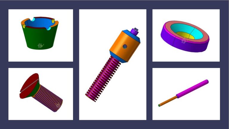
PARTS DESIGN AND ASSEMBLY :-
USING COMMANDS IN CATIA FOR UNIVERSAL COUPLING :-
PARTS OF UNIVERSAL COUPLING:-
1 .Selection of plane
2.Sketching the line and circle
3.Co nstrain the dimension
4. Symmetricity
5. Mirror line object
6. Trim the profile
7.Exit work bench
8. Pad the profile
9. Pocket
1 0. Project element
1 1 . Edge fillet
12. Views
13. Pan
14. Zoom fit
1 5. Existing component insert
1 6. Explode
17. Manipulation
18. Snap
19. Assembly tools

PROCEDURE :-
1 . Identify various parts to be created.
2. First enter into part environment and create the main part and create the main part of t he assembly.
3. First identify whether the main part or the first to be created by pad or by revolution.
4. Select the sketch tool and then select the coincidental plane option and select any one of the standard 3 planes (i.e. front, right &top) .
5. Create the cross-section profile as a closed one using the 2D commands available after complet ing the sketch, click open or return button and then click finish button.
6. For creating other parts, select sketch, then select the required plane.
7. Construct the full cross section for pportionand const ruct the half of the cross section and an axis line for a revolution.
8. Do the protrusions by using the protrusion command and the revolution by revolved
protrusion command.
9. For constructing holes and cutout, used hole command and cutout command.
10. If we use hole command, change the diameter of the hole by using modify menu, res ize hole option.
1 1 . Use revolved cutout command whenever needed.
12. Use the distance between option to maintain accurate distance between one edge and other edge or between one edge and to center the hole.
1 3. After constructing each part save it as a separate part file.
14. Enter into assembly environment.
15. Assembly the various parts construct parts properly construct using the various assembly constraints available
16. After finishing assembly, check whether the various parts have been connected pro perly or not by rotating the view.
17. Save the assembly as a file.


Conclusion:
Mechanical design is a complex undertaking, requiring many skills. The design and fabrication of a Universal coupling was done in this project work. In designing problem, safe torque on shaft was determined. The cross pin size (diameter) was determined considering bearing stress, shearing stress and bending stress taken into account. The application of a universal coupling also studied in this project work.